Minimum Leakage Flux Is Achieved Using Which Inductor
In the layer-wound coil a substantial reduction in leakage inductance Lp and Ls is obtained by interweaving the primary and secondary windings. View chapter Purchase book MATLABSimulink Ashok Kumar L.

Lbbm008121x8 V0e Inductors Coils Cores Nippon Chemi Con Corporation
Leakage inductance is that flux which does not couple to the other winding.

. Core losses and winding losses are strongly related to the frequency. The current ripple in a buck converter with coupled inductors changes to Equation 2 for D 1Nphases where ρ LmLk is a coupling coefficient Lm is magnetizing or mutual inductance. Electronic technicians talk about hard transformers since large variations in the load coupled with low leakage inductance can produce large current spikes.
Core loss for a. Efficiency of the transformer energy loss does not worsen. Up to 24 cash back Leakage Flux EE Core c Ls--r-s c c C iil s -i r-E5 3 Figure 17-4.
Total full load current In. The current ripple in a buck converter with coupled inductors changes to Equation 2 for D 1Nphases where ρ LmLk is a coupling coefficient Lm is magnetizing or mutual inductance. Some flux will leak from the core and return to the air winding layers and insulator layers without linking the secondary windings.
1 these leakage inductances are defined in terms of transformer winding open-circuit inductances and associated coupling coefficient or coupling factor. To better appreciate the coupled inductor size notice that discrete. This particular equation is.
6 This particular equation is limited to D 1Nphases which is often enough in a lot of applications such as V. Leakage inductance but instead to utilize it for a specific purpose. Final conclusion is if leakage flux is low machine will demand less magnetizing current.
Lk is a leakage inductance and Nphases is the number of coupled phases. The magnetic circuits flux that does not interlink both windings is the leakage flux corresponding to primary leakage inductance L P σ and secondary leakage inductance L S σReferring to Fig. Toff 1 53520000 43 x 10-5 seconds and fmin 1 52543 x 10-5 seconds 18700 Hz.
Leakage fluxes by a coaxially wound transformer In electronic power supplies ring core transformers are frequently used. But such slots increases the average airgap between stator and rotor which again increases the magnetizing current. Flux21 is the flux in 2 from 1 flux11 is the flux in 1 from 1 etc.
If you have two inductors then the flux leakage is any flux that isnt flux linkage the self flux is flux leakage. The standard transformer with a single primary and. Jan 17 2015.
But for inductors with very high AC current components this leakage flux can cause very substantial increases in the AC wire resistance. As a result higher voltage For the transformer with minimum leakage inductance the real turns ratio is close to B 7B. Calculate the off-time and minimum switching f min of the transistor switch using equations 2 and 3.
Coupled inductor windings L 1 2. Uncoupled leakage inductance LL. If the stars in heaven are aligned perfectly none of this leakage flux will make a loop around the window of the core.
Phase- staggering operation of multiple bidirectional dcdc converters in parallel connection is considered to reduce the ripple size of summed inductor currents and mitigate the filtering requirement for the battery charging current. For the coupled inductor design in Figure 6 the leakage flux goes into a plate right on top of the windings returning in a very short vertical loop while the coupling fluxes run in horizontal loops around the main core between the windings. A reduction in inductor current ripple by a coupled inductor in.
In the design process finite element eddy. The ratio of the total flux produced to the useful flux set up in the air gap of the magnetic circuit is called a leakage coefficient or leakage factor. The useful flux when sets up in the air gap it tends to bulge outward at b and b as shown in above figure because of this bulging the effective area of.
For a filter inductor this is not an issue. So if you have a single inductor then I assume that there is no flux linkage and that L fluxN i L11. The area reduction of 18x and the saturation improvement of 15x are achieved simultaneously.
Operate as current-mode controllers. At a distance those fluxes will cancel each other out. Accurate Inductor Loss Determination Using Würth Elektroniks REDEXPERT Fig 1.
It is denoted by λ. Achieved by various power electronic techniques. So the application is better satis-fied with a low frequency core with a more square window shape.
So semi slots are preferred for induction machines. Uma Maheswari Y in Software Tools for the Simulation of Electrical Systems 2020. Curve not match the curve calculated using the FHA method 3 and the leakage inductance on the secondary side will result in voltage rising on the SR-MOSFET especially for high current low voltage applications.
Power high-frequency inductor are minimum losses and low leakage flux. Of course there is bound to be be some. B-H Curve The second type of core loss is due to eddy currents which are induced in the core material by a time-varying flux.
Due to the construction method they have a minimum leakage reactance. Practical applications of integrated inductors Though coupled integrated inductors demonstrate additional valuable features compared to non-coupled integrated inductors there are. It is simply a few turns of wire on an iron core that is not coupled to the other winding - exactly like a stand alone inductance.
It is not a source of loss per se. The primary open-circuit self. Lk is a leakage inductance and Nphases is the number of coupled phases.
And so that flux is total leakage flux. Only the leakage flux stores the energy in coupled inductors so the energy storage for the example shown in Figure 2 is associated with 50nHphase instead of a 210nHphase. However there will be some flux near each wire.
Hence for good efficiency leakage flux should be low which is possible with open type slots. According to Lenzs Law a changing flux induces a current that induces a flux in opposition to the initial flux. For all practical purposes you could say that the flux in the core is 0.
Reactance does not cause power loss. Here a minimum loss design of a 100 kHz inductor with foil windings using a multi air gap approach is presented. Calculate L using equation 5.
Basic Definition of Leakage Inductance In a typical transformer the flux generated by ac current excitation in the primary winding follows the magnetic circuit and link with the secondary winding. The above air gap allows lots of leakage flux to impinge on the wire windings. With only leakage flux stored in the coupled inductors they can be fabricated in much smaller footprints than discrete inductors.
Let the maximum ripple currenti through the inductor be i 2 1 2 amperes by equation 4. So a flux density limit of about 50100 mT would be a better choice for a ferrite-based energy storage inductor in a PFC circuit to prevent significant core heating due to these magnetization losses.

Uses Of Inductor Inductor Functions Practical Application
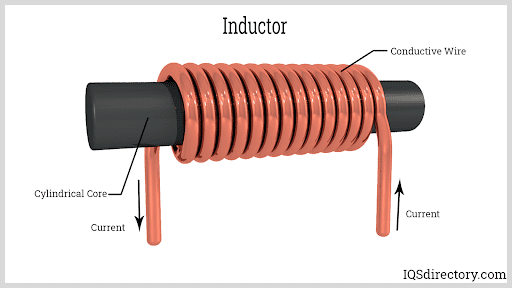
Inductors And Inductor Coils Basic Principles Types Inductance And Applications

Inductor And The Effects Of Inductance On An Inductor

Medium Waveband Coil Radio Shortwave Radio Crystals
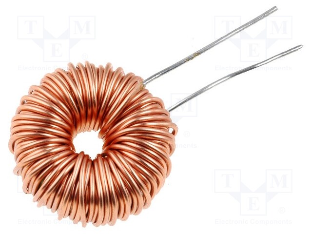
Dpo 3 0 470 Talema Inductor Wire Tht 470uh 3a 187mw Dpu470a3 Tme Electronic Components
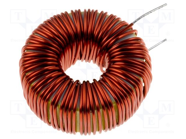
Dpo 3 0 470 Talema Inductor Wire Tht 470uh 3a 187mw Dpu470a3 Tme Electronic Components

Storage Chokes And Power Inductors

Leakage Inductance As A Function Of The A Number Of Nb Turns And Download Scientific Diagram

Variation Of The Leakage Inductance A Calculated For Four Different Download Scientific Diagram

Comparison Between Leakage Inductance Values Obtained From Simulations Download Table
The Role Of Magnetizing And Leakage Inductance In
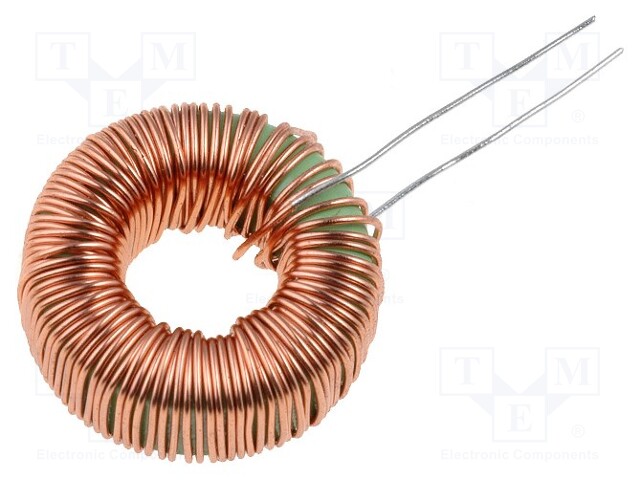
Dpo 3 0 470 Talema Inductor Wire Tht 470uh 3a 187mw Dpu470a3 Tme Electronic Components

Smd 2ln 1 22a Choke Mode Common Common Mode Inductor Coil P0502nlt Pulse Filter Custom Factory China Common Mode Inductor Coil Smd Power Inductors Made In China Com

Toroidal Inductors Current Compensated Chokes And Beads
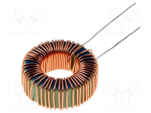
Dpt100a1 Ferrocore Inductor Wire Tht 100uh 240mw 1a Tme Electronic Components

Comments
Post a Comment